

In the interest of continuing product development, Kenworth reserves the right to change specifications or products at any time without prior notice.
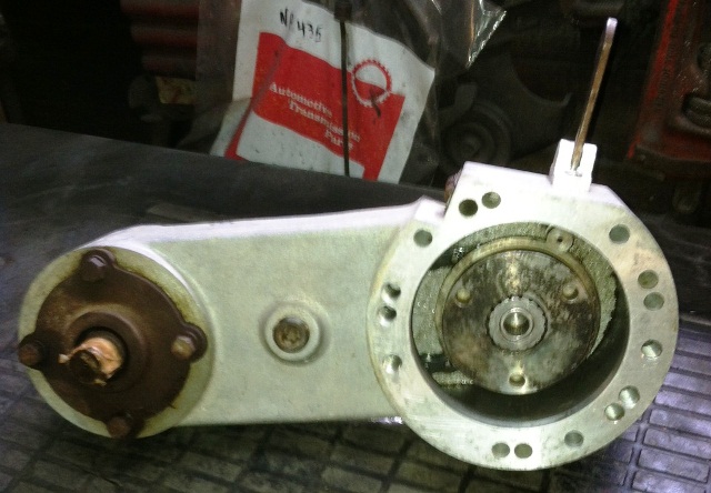
#SPICER PTO MODEL C 41 PROFESSIONAL#
Early in the process, professional body builders can often contribute valuable information that reduces the ultimate cost of the body installation.


#SPICER PTO MODEL C 41 MANUAL#
The Body Builder Manual can be very useful when specifying a vehicle, particularly when the body builder is involved in the vehicle definition and ordering process. This manual contains appropriate dimensional information, guidelines for mounting bodies, guidelines for modifying frames, electrical wiring information, and other information useful in the body installation process.This manual is specific to chassis with 2010 engines. This information will be helpful when installing bodies or other associated equipment. This manual was created to provide body builders with appropriate information and guidelines useful in the body planning and installation process. įIGURE 6-10: Crossmember-Gusset Hole PatternįIGURE 6-11: Acceptable U-Bolt Mounting with Wood and FabricatedįIGURE 6-12: Clearance Space for Air Lines and CablesįIGURE 6-13: Example of Fishplate Bracket at Rear End of Body,įIGURE 7-1: Detail of Frame Extension and Joint WeldingįIGURE 7-3: Comparison of Original, Shortened, andįIGURE 7-4: Crossmember Added When Distance ExceedsįIGURE 8-3: Multiplexed Instrumentation Block Diagram.įIGURE 8-5: Instrument Cluster ComponentsįIGURE 8-7: Firewall Air Junction Block (View from inside of cab)įIGURE 8-8: Air Filter Restriction Sensor on Firewall Air Junction BlockįIGURE 8-9: Fuel Filter Restriction Pressure Gauge Sensor LocationįIGURE 8-10: Telltale Symbol Standard Cards įigure 2-4: Aerodynamic Mirror OAT Sensor Locationįigure 2-5: Instrument Cluster for T4/T6/T8/W9/C5įigure 3-1: Prospecter Turn Circle AnalysisįIGURE 4-1: Measurement Location of DEF Supply Module (Pump)įIGURE 4-2: Measurement Location of DEF Dosing Module (Injector)įIGURE 4-4: RH Under Cab Exhaust with Small, Medium, or Large Tanks.įIGURE 4-5: Horizontal Exhaust with Small, Medium, or Large Tanks.įIGURE 4-6: Vertical Exhaust with Small, Medium, or Large Tanks.įIGURE 4-7: RH Under Cab Exhaust with Clear Back of Cab Tank.įIGURE 4-8: Vertical with Clear Back of Cab TankįIGURE 4-9: Routing DEF Lines and DEF TrapįIGURE 4-10: Supply Module Allowed Clocking AnglesįIGURE 4-11: Isometric View of Right Hand Under DPF and SCRįIGURE 4-12: Top View of Right Hand Under DPF and SCR withįIGURE 4-13: Right View of Right Hand Under DPF and SCR with SingleįIGURE 4-1 4: Back View of Right Hand Under DPF and SCR with SingleįIGURE 4-15: Isometric View of Right Hand Under DPF and SCR withįIGURE 4-16: Top View of Right Hand Under DPF and SCR with DualįIGURE 4-17: Right View of Right Hand Under DPF and SCR with DualįIGURE 4-18: Back View of Right Hand Under DPF and SCR with DualįIGURE 4-19: Isometric View of Right Hand Under DPF and SCR onįIGURE 4-20: Top View of Right Hand Under DPF and SCR on AerocabįIGURE 4-21: Right View of Right Hand Under DPF and SCR on AerocabįIGURE 4-22: Back View of Right Hand Under DPF and SCR on AerocabįIGURE 4-23: Isometric View of Right Hand Under DPF and SCR onįIGURE 4-24: Top View of Right Hand Under DPF and SCR on AerocabįIGURE 4-25: Right View of Right Hand Under DPF and SCR on AerocabįIGURE 4-26: Back View of Right Hand Under DPF and SCR on AerocabįIGURE 4-27: Isometric View of Horizontal DPF and SCR withįIGURE 4-28: Top View of Horizontal DPF and SCR withįIGURE 4-29: Right View of Horizontal DPF and SCR withįIGURE 4-30: Back View of Horizontal DPF and SCR withįIGURE 4-31: Isometric View of Vertical DPF and SCRįIGURE 4-32: Top View of Vertical DPF and SCRįIGURE 4-33: Right View of Vertical DPF and SCRįIGURE 4-34: Back View of Vertical DPF and SCRįIGURE 6-1: Isometric View of T800 FEPTO front end withįIGURE 6-2: T800 FEPTO front end with 66” Bumper SettingįIGURE 6-3: Isometric View of T800 FEPTO front end withįIGURE 6-4: T800 FEPTO front end with 73” Bumper SettingįIGURE 6-5: Minimum Clearance Between Top Of Rear Tires AndįIGURE 6-6: Minimum Back of Cab ClearanceįIGURE 6-7: Spacer Between Frame Sill and Body Rail - Rubber or Plastic 6-5įIGURE 6-9: Rubber Spacer Between BracketsBetween the Mountingīolt and Upper Bracket. MULTIFUNCTION TURN SIGNAL STALK, CHASSIS NODE & CHASSIS LOAD CENTERįigure 2-1: Incomplete Vehicle Certification Documentįigure 2-2: Locations of Certification Labels - Driver’s Door and Frameįigure 2-3:vWest Coast Mirror OAT sensor. SPARE RELAYS BODY BUILDER INSTALLED(For loads exceeding 20 amps) Installation Requirements and Dimensions for DEF System T800 with FEPTO (Front Engine Power Take Off) FEDERAL MOTOR VEHICLE SAFETYSTANDARDS COMPLIANCE


 0 kommentar(er)
